Views: 131 Author: Site Editor Publish Time: 2020-12-24 Origin: Site
If you are considering buying an LED Display, you may have some questions, just in case, something goes wrong with your LED display. Or you have an LED display and are trying to solve the problem. Either way, please keep reading to understand this problem, the severity of this problem, and the LED display troubleshooting guide in this LED display troubleshooting guide.

1. Resistance detection method, adjust the multimeter to the resistance range, detect the resistance value of a certain point of a normal circuit board, and then detect the same point of another same circuit board to test whether the resistance value is different from the normal resistance. If they are different, the scope of the problem is determined.
2. With the voltage detection method, set the multimeter to the voltage range, detect the ground voltage at a certain point of the circuit suspected of having a problem, and compare whether it is similar to the normal value, otherwise, the scope of the problem is determined.
3. Short-circuit detection method, set the multimeter to the short-circuit detection gear (some are diode voltage drop gears or resistance gears, usually with alarm function) to detect whether there is a short-circuit phenomenon, and the short-circuit should be solved first to prevent it from burning Other devices. This method must be operated when the circuit is powered off to avoid damage to the meter.
4. Voltage drop detection method, adjust the multimeter to the diode voltage drop detection gear, because all ICs are composed of a large number of basic single components, but are miniaturized, so when there is a current passing through a pin of it, there will be a voltage drop across the pin. Generally, the voltage drop on the same pin of the same type of IC is similar. According to the voltage drop value on the pin, it is necessary to operate with the circuit power off. This method has certain limitations. For example, if the tested device is high-impedance, it cannot be detected.
A. The whole LED board is not bright.
1. Check whether the power supply is connected to the signal line.
2. Check whether the test card recognizes the interface. If the red light of the test card flashes, it is not recognized. Check whether the light board and the test card have the same power ground, or the light board interface has a signal and ground short circuit, which makes the interface unrecognizable. (Smart Test Card)
3. Check whether the 74HC245 is short-circuited with solder and whether the corresponding enables (EN) signal input and output pins on the 245 are soldered or short-circuited to other circuits. Note: Mainly check the power supply and enable (EN) signal.
B. When the dots are scanned obliquely, the regular interlace is not bright and the screen is overlapped
1. Check whether there are any disconnection, virtual welding, or short circuit between the A, B, C, and D signal input ports to 245.
2. Check whether the A, B, C, D output terminals corresponding to 245 are open circuit, virtual welding, or short circuit between 138.
3. Check whether the signals A, B, C, D are short-circuited or a signal is short-circuited to ground. Note: Mainly detect ABCD line signals.
C. One or several lines are not bright when all on
Detect whether the circuit between 138 and 4953 is open, soldered, or short-circuited.
D. During line scanning, two or several lines (usually a multiple of 2, regular) are lit at the same time
1. Check whether the signals of A, B, C, D are short-circuited.
2. Check whether the 4953 output terminal is short-circuited with other output terminals.
E. Single point or multiple points (irregularly) do not light up when all on
1. Find the corresponding control pin of the module and measure whether it is short-circuited with this line.
2. Replace the module or a single lamp.
F. One or more columns are not bright when all on
Find the pin that controls the column on the module, and check whether it is connected to the output terminal of the driver IC (74HC595/TB62726...).
G. There is a single point or a single column highlight, or the entire line is highlighted, and it is not controlled
1. Check whether the column is short-circuited with the power ground.
2. Check whether the line is short-circuited with the positive pole of the power supply.
3. Replace its driver IC.
H. The display is chaotic, but the signal output to the next board is normal
Detect whether the STB latch output terminal corresponding to 245 is connected to the latch terminal of the driver IC or the signal is short-circuited to other lines.
I. The display is chaotic and the output is abnormal
1. Check whether the STB signal latched by the clock CLK is short-circuited.
2. Check whether the clock CLK of 245 has input and output.
3. Check whether the clock signal is short-circuited to other lines. Note: Mainly detect clock and latch signals.
J. Display lack of color
1. Check whether the data terminal of the color of 245 has input and output.
2. Check whether the data signal of this color is short-circuited to other circuits.
3. Check whether the cascaded data ports between the driver ICs of the color are open, shorted, or soldered.
(Note: The voltage detection method can be used to find the problem more easily, check whether the voltage of the data port is different from the normal one, and determine the fault area.)
K. Problem with output
1. Check whether the line from the output interface to the signal output IC is connected or short-circuited.
2. Check whether the clock latch signal of the output port is normal.
3. Check whether the cascade output data port between the last drive IC is connected to the data port of the output interface or whether it is short-circuited.
4. Whether the output signals are short-circuited to each other or short-circuited to the ground.
5. Check whether the output cable is good.
L. The cell board appears at 8 or 16 points in rows, columns, or single points that are not bright, long bright, dark bright
1. Visually check whether the module pins and leads corresponding to the fault are short-circuited, soldered, or disconnected.
2. In each cell (the unit board is divided into upper and lower cells), whether the common connection line between the upper and lower modules and the left and right modules is normal (set the multimeter to the bell end, the line input end of the measurement module and the lead wire of each control input end). If yes, It is judged that the module is bad or not, it can be eliminated by replacing it with a thin wire.
3. Use a multimeter to directly measure whether a single module is normal. If yes, it is judged as an internal short circuit between the circuit board and the module. Otherwise, it is judged as the module is broken and replaced with a module of the same model.
M. Several rows or whole cells appear on the cell board (the cell board is divided into upper and lower cells) not bright, long bright, dark bright.
1. Visually inspect the corresponding line tube, through-core inductance, and integrated circuit for virtual welding, short circuit, or open circuit. If yes, disconnect the short circuit and re-weld the open circuit.
2. Use a multimeter to measure whether the voltage of each line tube output terminal is normal (multimeter measurement method: connect the black test lead to GND and the red test lead to measure the voltage of each pin); if yes, the judge that the line output terminal is disconnected from the corresponding module pin; If not, measure whether the input terminal of the line tube is normal; if yes, then the line tube is broken, replace it with the same model tube; if not, whether the output terminal of the HC138 corresponding to the measurement is normal; if yes, judge whether the output terminal of the HC138 is normal. The input end of the tube is open; if not, it is judged that the HC138 is broken.
3. Replace with a good 16P cable, measure the voltage of HC138 address input terminals 1, 2, and 3 pins, strobe terminals 4, 5 (active low), 6 (active high), an integrated circuit power supply Whether it is normal or not, if yes, it is judged that the HC138 is bad, and then continue to check with (2). (4) Whether the 5V connection line between the two small areas is disconnected, if yes, it can be connected directly with the same power line (the general phenomenon is that the whole area is not bright or dark).
4. Measure the line signal of the input terminal of the unit board (the golden finger 26P can be regarded as 13 groups, of which 8, 9, 10, 11 are four groups of line signals L0, L1, L2, and L3) for internal short circuit, open circuit and input HC244 Whether the rear-drive is normal, if yes, measure whether the signal input to the HC138 by the HC244 drive is normal, and then continue to check with (2), if not, it is judged that the HC244 is bad and replace it with an integrated circuit of the same model.
N. There is no red or green on the cell board (the cell board is divided into upper and lower cells)
1. Visually inspect the integrated circuit corresponding to the fault, whether the 26P cable has false soldering, open circuit, and whether the 5V power supply is normal (you can directly replace it with a good 26P cable).L. The cell board appears at 8 or 16 points in rows, columns or single points that are not bright, long bright, dark bright
1. Visually check whether the module pins and leads corresponding to the fault are short-circuited, soldered, or disconnected.
2. In each cell (the unit board is divided into upper and lower cells), whether the common connection line between the upper and lower modules and the left and right modules is normal (set the multimeter to the bell end, the line input end of the measurement module and the lead wire of each control input end). If yes, It is judged that the module is bad or not, it can be eliminated by replacing it with a thin wire.
3. Use a multimeter to directly measure whether a single module is normal. If yes, it is judged as an internal short circuit between the circuit board and the module. Otherwise, it is judged as the module is broken and replaced with a module of the same model.
O. Trouble phenomenon: the cell board appears in the cell (the cell board is divided into upper and lower cells). The upper and lower modules in the middle are all lack red or green, or are lack red or green from the abnormal place to the end.
1. Visually check whether the integrated circuit corresponding to the fault on the unit board, such as HC595, is soldered, short-circuited, or open; if so, solder the pins well.
2. Check whether the 5V power supply is normal.
3. Use a multimeter to measure the 14-pin input terminal of the HC595 corresponding to the fault [When measuring the HC595, you should distinguish the redintegrated circuit, the order is: red, green (R, G) HC595 9-pin is the signal output terminal, 14-pin is Signal input terminal] Whether the voltage is normal; If yes, the judge that the HC595 is bad (under other normal power supply conditions), and replace it with an integrated circuit of the same model; if not, check the voltage and circuit connection of the 9-pin output terminal corresponding to the HC595. Whether the line is disconnected, if not, it is judged that the HC595 is broken and replaced with the HC595 integrated circuit of the same model (when replacing the integrated circuit HC595, be careful not to disconnect the circuit lead).
1. One group of LED module is not bright or abnormal:
Check if the cable of the first abnormal LED module in the signal direction is in good contact with the power cord. If the LED module has no LED light, it means that there is no power input. Please check the power part (use a multimeter to check), if there are patterns (color confusion) The highlight) indicates that the module has no signal input. Please check whether the input end of the first abnormal module's flat cable is in close contact. It can be plugged and unplugged multiple times. If there is a problem, you can still replace the new flat cable.
2. Single LED module does not light up:
Check whether the power supply of the module is good or not, mainly check whether the power socket on the module is loose. If the color of the whole module is chaotic or inconsistent (but there is signal input, there is a correct picture), it means that the signal transmission line is poorly connected. Re-plug the flat cable, or replace the tested flat cable. If you still have the same problem after replacing a good cable, please check whether there is a problem with the PCB board interface.
3. Detection method of a single light, not lighting problem:
Use a multimeter to check whether the LED is damaged. If the lamp is broken, replace it according to item 5 below. Specific lamp test method: set the multimeter to resistance X1, connect the black test lead of the analog multimeter to the positive pole of the LED, and connect the red test lead to the negative pole (digital meter black pen connects to negative, red pen connects to positive), if the LED is on, the measured light is Yes, if the light is not on, the measured light is broken.
4. LED dead pixel maintenance (out of control point):
If the LED is confirmed to be damaged after a single lamp inspection, the following maintenance methods can be selectively adopted according to actual needs.
4-1. Front maintenance: Use a screwdriver of the corresponding model to remove the screws of the fixed mask from the front (note the screws for good intentions), remove the mask, and replace the lamp (please change the lamp according to the following lamp replacement method), replace the lamp and gel After the sealing is over, restore the original mask, tighten the screws (be careful not to press the lamp when screwing), and finally, if any glue remains on the surface of the LED, please carefully remove the glue.
4-2. Back maintenance: Use a screwdriver of the corresponding model to remove the screws from the back (note the well-intentioned screws), and unplug the signal cable. For safety, please do not unplug the power cable to prevent accidents. Be careful to remove the module Take it out of the sheet metal hole, move it to the back of the box, and then perform maintenance and replacement of a single module in accordance with the front maintenance method (please replace the lamp in the following method) or overhaul others.
5. Change the light:
Use a sharp tool (such as tweezers) to remove the colloid around the damaged LED, and make the LED pins clearly visible in the line of sight. Use the tweezers to clamp the LED with your right hand, and use the soldering iron with your left hand (the temperature is about 40 degrees Celsius, too high a temperature will lead damage) Touch the solder, and stay for a while (no more than 3 seconds, if the time exceeds the time but does not meet the disassembly requirements, please cool down and try again) melt the solder, and remove the LED with tweezers. Insert the LED lamp that meets the requirements into the hole of the PCB circuit board. (The long leg of the LED lamp is the positive pole and the short leg is the negative pole. The "square hole" on the PCB is the LED positive pin socket, and the "round hole" is the LED Negative pin jack), melt a little solder wire, glue it to the tip of the soldering iron, use tweezers to adjust the direction of the LED to make it stable, solder the solder to the connection between the LED and the PCB, use the same type of gel (PH value = 7) Seal the LED.
A. The whole LED Screen is not bright (Black Screen)
1. Check whether the power supply is energized.
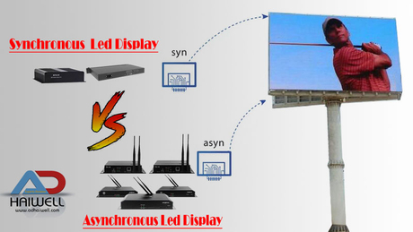
2. Check whether the communication line is connected and whether it is connected incorrectly. (Sync LED screen)
3. The synchronization LED screen detects whether the green light of the communication between the LED sending card and the LED receiving card flickers.
4. Whether the computer monitor is protected, or the display area of the LED screen is black or pure blue. (Sync LED screen).
B. The whole LED unit board is not bright (black screen)
1. The horizontal direction of several consecutive LED boards is not bright, check whether the cable connection between the normal unit board and the abnormal unit board is connected; or whether the chip 245 is normal,
2. The longitudinal direction of several consecutive boards is not bright, check whether the power supply of this column is normal.
C. The unit board does not light up
1. Check whether the line pin is connected to the 4953 output pin.
2. Check whether 138 is normal.
3. Check whether 4953 is hot or burned.
4. Check whether 4953 has a high level.
5. Check whether the control pins 138 and 4953 are connected.
D. The unit board does not light up
1. Check whether 595 is normal.
2. Check whether the corresponding pass pins of the upper and lower modules are connected.
3. Check if there is a connection between the 595 output pin and the module pin.
E. Lack of color on the cell board
1. Check whether the 245 R.G data is output.
2. Check whether the normal 595 output pin is connected to the abnormal 595 input pin.
3. Check whether the signals of A, B, C, D are short-circuited.
4. Check whether the 4953 output terminal is short-circuited with other output terminals.
F. Single point or multiple points (irregularly) do not light up when all on
1. Find the corresponding control pin of the LED module and measure whether it is short-circuited with this line.
2. Replace the module or a single LED lamp.
G. One or more LED columns are not bright when all on
1. Find the pin that controls the column on the LED module, and check whether it is connected to the output terminal of the driver IC (74HC595/TB62726).
2. Visually check whether the LED module pins and integrated circuits corresponding to the fault on the unit board are soldered, short-circuited, or open; if so, solder the pins well.
3. Measure the output terminal of HC595 with a multimeter, the output pins of HC595: 1, 2, 3, 4.
1. The whole LED screen is not bright or there are squares
·LED Display Control whether the host is turned on
·Whether the communication line is plugged in
·Is the LED sending card inserted?
·Whether the data lines between the LED multimedia card and the capture card and the LED sending card are well connected
The position of the LED receiving card JP1 or JP2 switch is wrong
·Open the host
·Plug in the communication line
·Reinsert the LED sending card
Connect the data cable between the LED multimedia card and the capture card, and the LED sending card.
·Adjust JP1 and JP2 switch positions
·Whether the computer monitor is protected, or the LED display area of the LED screen is black or pure blue. (Sync LED screen)
2. Every time you start the LED studio, it prompts that the signal collection line from the COM port of the control system to the data sending card is not connected or the COM port of the computer itself is broken.
·Connect the data cable or replace the computer
3. The whole LED screen is shaking or ghosting
·Check the communication line between the computer and the large LED screen
·Check the DVI cable of the LED multimedia card and the LED sending card.
·The LED sending card is broken.
Re-insert or replace the communication cable. Insert and reinforce the DVI cable. Replace the LED sending card.
1. One LED unit board does not light up
Whether +5V power or GND is supplied
·+5V and GND are short circuits
·138 Is the OE signal of the fifth leg present?
· 245 connected OE signal is normal (open circuit or short circuit);
·Supply +5V or GND
·Disconnect the short circuit
·Supply the OE signal
·Connect the open circuit and disconnect the short circuit
2. Half or lower part of a unit board is not bright or displayed abnormally
·Whether there is an OE signal on the 5th leg of 138;
·Whether the signals of the 11th and 12th legs of 74HC595 are normal (SCLK, RCK)
·Whether the connected OE signal is normal; (open circuit or short circuit)
·Whether the SCLK and RCK signals of the dual-row pins connected to 245 are normal; (open circuit or short circuit)
·Connect the OE signal
·Connect SCLK and RCK signals well
·Connect the open circuit and disconnect the short circuit
·Connect the open circuit and disconnect the short circuit
3. A row on a unit board or the row of a corresponding LED module is not bright or displayed abnormally
·Check whether the line signal pins of the corresponding LED module are soldered or missed;
·Check whether the corresponding pin of the row signal and 4953 is disconnected or short-circuited with other signals
·Check whether the up and down resistance of the line signal is not soldered or missed
·Whether the line signal output by 74HC138 and the corresponding 4953 is disconnected or short-circuited with other signals
·Welding the missing and missing welding
·Connect the open circuit and disconnect the short circuit
·Fix the unsoldered ones and weld the missing ones
·Connect the open circuit and disconnect the short circuit
4. One LED unit board has two lines on at the same time (one line is normal and one line is always on when displaying text)
·Check if the two lines of signals corresponding to the LED module are short-circuited
· Check to see if the output leg of 138, pull-up and pull-down resistance, module pin and 4953 are short-circuited
·Disconnect the short circuit
5. The upper or lower part of red or green is not bright or displayed abnormally
·Check whether the input row pins are normal or short-circuit with GND, +5V
·Check whether the signal between the input header and 245 is normal (short circuit or open circuit)
·IC245 is broken "Connect the broken circuit well
·Disconnect the short circuit
·Replace IC
Step 1: Check whether the computer graphics card setting part is set up properly. The setting method is in the CD-ROM electronic file as needed, please refer to it.
Step 2: Check the basic connection of the system, such as the DVI cable, whether the network cable socket is correct, the connection between the main control card and the computer PCI socket, the serial cable connection, etc. The connection method has been illustrated, please refer to it carefully
Step 3: Check whether the computer and LED power system meet the usage requirements. When the power supply of the LED screen body is insufficient, when the display is close to white (high power consumption), it will cause the screen to flicker. Prepare a suitable power supply according to the power demand of the cabinet.
Step 4: Check whether the green light of the LED Novastar sending card is flashing regularly: flashing to step 6, if it does not flash, restart, check whether the green light is flashing regularly before entering win98/2k/XP, if flashing, go to step 2. Please check whether the DVI cable is connected properly. If the problem is not solved because one of the sending card, graphics card, and DV cable is faulty, please replace it separately and repeat step 3.
Step 5: Please follow the software instructions to set or reinstall and then set again, until the green light of the sending card flashes, otherwise repeat step 3.
Step 6: Check whether the green light (data light) of the receiving card flashes synchronously with the green light of the sending card. If it flashes, go to step 8, and check whether the red light (power) is on. If it’s on, go to step 7, and if it doesn’t light, check the yellow light (power). Protection) is on, if it is not on, check whether the power supply is connected reversely or there is no power output, if on, check whether the power supply voltage is 5V, if it is turned off, remove the adapter card and the cable and try again. If the problem is not solved, the LED receiving card is faulty, Replace the LED receiving card, repeat step 6.
Step 7: Check whether the network cable is well connected or too long (you must use a standard Category 5 network cable, and the longest distance of the network cable without a repeater is less than 100 meters), and check whether the network cable is made according to the standard (please refer to the system installation and setting ), if the problem is not resolved, the receiving card is faulty, replace the receiving card and repeat step 6.
Step 8: Check whether the power light of the large screen is on, if not, go to step 7 to check the interface definition line of the adapter card
Whether it matches with the cell board.
Note: After most of the screens are connected, there may be no screen or blurry screen in some cabinets. The signal is not transmitted because the RJ45 interface of the network cable is not connected firmly, or the power of the receiving card is not connected, so please re-plug The network cable (or exchange), or plug in the power supply of the receiving card (note the direction) can solve the problem.
A. The whole screen is not bright (black screen)
1. Check whether the power supply is energized.
2. Check whether the communication line is connected and whether it is connected incorrectly. (Sync LED screen)
3. The synchronization LED screen detects whether the green light of the communication between the LED sending card and the LED receiving card flickers.
4. Whether the computer monitor is protected, or the LED display area of the LED screen is black or pure blue. (Sync LED screen)
B. The whole unit board is not bright (black screen)
1. The horizontal direction of several consecutive boards is not bright, check whether the cable connection between the normal unit board and the abnormal unit board is connected; or whether chip 245 is normal.
2. If several consecutive boards are not lit in the longitudinal direction, check whether the power supply of this column is normal.
C. The unit board does not light up
1. Check whether the line pin is connected to the 4953 output pin.
2. Check whether 138 is normal.
3. Check whether 4953 is hot or burned.
4. Check whether 4953 has a high level.
5. Check whether the control pins 138 and 4953 are connected.
D. The unit board does not light up
1. Check whether 595 is normal.
2. Check whether the corresponding pass pins of the upper and lower modules are connected.
3. Check if the 595 output pin is connected to the module pin.
E. The unit board lacks color
1. Check whether the 245 R.G data is output.
2. Check whether the normal 595 output pin is connected to the abnormal 595 input pin.
Let's light up the future of advertising together
Mon - Fri: 9 AM - 6 PM
Sat - Sun: 11 AM - 3 PM


 English